
Shoutout to Dave for all the helpful discussions over on discord!
This article initially began as a short post discussing strategies that can determine rectangle intersections and collisions, for both axis-aligned rectangles as well as arbitrarily rotated rectangles. While working on a recent project however, I discovered that this intersection test can be extended to not only return the polygonal shape that is formed by the intersection of two non-axis aligned rectangles but also that of two convex polygons. Hence I extended the post to include this information as well.
We will also have a look at how to compute the intersection of two line segments in addition to a method that can determine if a point is contained within a polygonal shape (point in polygon test), both of which are important components of the polygon intersection test. In that manner this post covers a lot of ground, but for the sake of completeness I didn't want to leave anything out.
Lastly a note on terminology, for the most part I'll be using the words intersection and collision interchangeably, since they essentially mean the same thing: that two rectangles are touching or overlapping in some manner. Albeit this, the word collision implies movement on behalf of the two rectangles and is probably better suited in that context.
The methods described in this post might not be the most efficient ones for larger numbers of rectangles, but make up for that in simplicity. Here's a quick index to the different sections of the article:
Quick Index
- What's Axis-alignment?
- Axis-aligned Rectangle Collision
- Drawing rotated Rectangles
- Intersection of two Line Segments
- Point in Polygon Test
- Drawing the Intersection Polygon
- Beyond Rectangles: Polygon Intersections
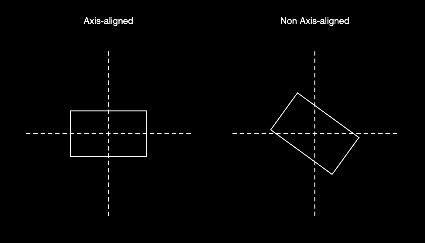
What's axis-alignment?
The term axis-aligned indicates that a shape is aligned with the coordinate axes. For example an axis-aligned rectangle would have it's edges parallel to the x and y axes. Something that isn't axis aligned can occur with a different orientation such that it lies rotated with respect to the coordinate axes. Here's an example:
Dealing with axis-aligned rectangles greatly simplifies certain tasks, like determining if they intersect for example. I've already mentioned this in a section of a previous article: A Simple Solution for Shape Packing in 2D, but axis-aligned rectangles are super useful when you need to determine collisions of some type in an efficient manner. Collision detection is a rather common problem in video games, where it's often of crucial importance that the algorithm used to determine these collisions is fast. A popular approach in video games is dividing the problem into two phases, a broad phase where we determine objects in the scene that could potentially collide, which are then doubled down on in the narrow phase where the actual collisions are detected. Axis aligned bounding boxes (rectangles) are popularly utilised as such a broad phase algorithm, because their collision is relatively cheap to compute. In the next section we'll have a look at how this works!
Axis-aligned Rectangle Collision
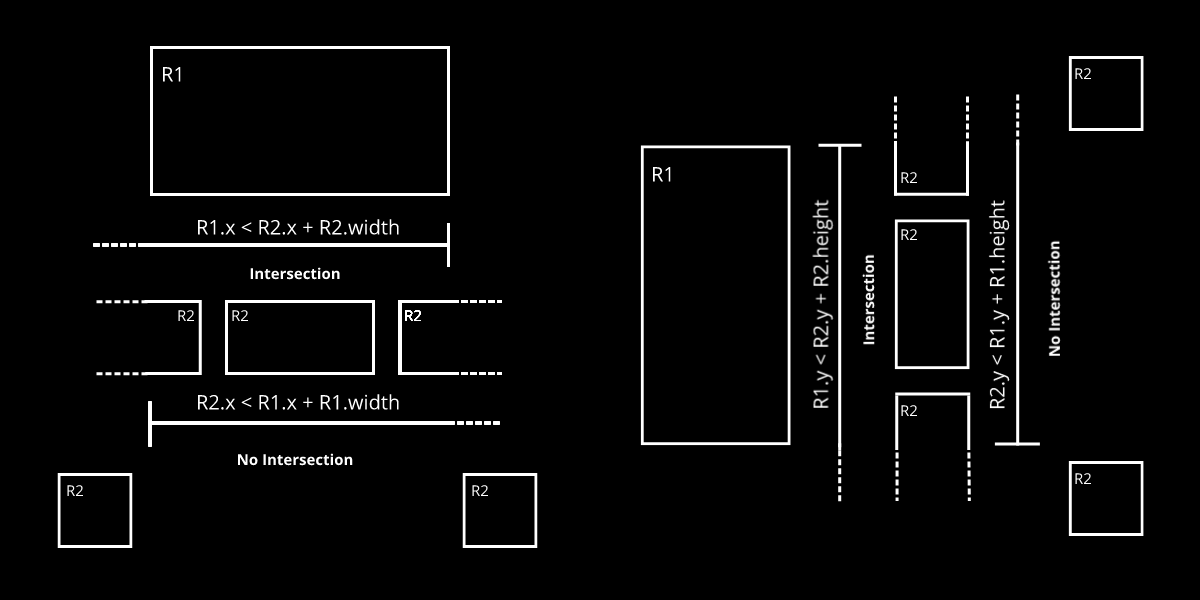
A rectangle can be represented by four numbers, two that represent it's x and y coordinate, usually indicating the top left corner, as well as two numbers that represent its width and height starting from that positional coordinate. The intersection of two axis-aligned rectangles can then be verified when the following four conditions are fulfilled:
\( x_{R1} < x_{R2} + width_{R2} \)
Left bound of R1 less than right bound of R2
\( x_{R2} < x_{R1} + width_{R1} \)
Left bound of R2 less than right bound of R1
\( y_{R1} < y_{R2} + height_{R2} \)
Top bound of R1 less than bottom bound of R2
\( y_{R2} < y_{R1} + height_{R1} \)
Top bound of R2 less than bottom bound of R1
Reading these might be a bit confusing at first, but essentially these checks determine how the edges of the two rectangles are situated with respect to each other. In this scenario intersection along an axis can be determined with two conditions, along the x axis for example, one that checks if the left edge of R1 is somewhere to the left of R2's right edge AND one that checks if R2's left edge is somewhere to the left of R1's right edge. Combining both conditions, we're essentially checking if at least one edge of one rectangle is situated between the edges of the other rectangle, in which case the rectangles are overlapping in some manner. More generally it means that the two rectangles are covering a shared range of x coordinates at the same time.
Taking either one of these conditions individually doesn't tell us much about the position of the rectangles, if both hold however we can say that they are intersecting, along the x axis at least. We then need to repeat the same along the y axis to actually determine if they're intersecting on the 2D plane. If this was confusing maybe the visual aid underneath will help:
And now to put this idea into code! To make things a bit more manageable we'll create our own custom rectangle class such that we can later give it the ability to check for collisions with other rectangles. To represent a simple rectangle we don't need all that much as mentioned earlier, just two coordinates to store the position in addition to its dimensions. For the case of axis-aligned rectangles it makes sense to have the position coordinates of the rectangle represent the top left corner because it just makes calculations less wordy. It is also generally the default rectMode() in p5js:
// example of a minimal rectangle class
function makeRect(posx, posy, wid, hei){
  this.posx = posx
  this.posy = posy

  this.wid = wid
  this.hei = hei

  // function that draws the rectangle to the canvas
  this.display = function(){
    rect(this.posx, this.posy, this.wid, this.hei)
  }
}
Next up is the function that will allow us to determine if our rectangle intersects another one. The function accepts as input another rectangle object which we will need to verify how the two rectangles are situated with regard to each other:
this.checkCollision = function(otherRect){
  if( this.posx < otherRect.posx + otherRect.wid &&
      this.posx + this.wid > otherRect.posx &&
      this.posy < otherRect.posy + otherRect.hei &&
      this.posy + this.hei > otherRect.posy
    ){
    return true
  }
  return false
}
The check uses the exact same logic that we discussed a little bit earlier. The function will return true in case the rectangles are intersecting, and false otherwise. Let's test this with a simple example, hover your mouse over the sketch and drag it into the stationary rectangle, if everything works correctly the draggable rectangle should light up red when the two are intersecting:
We could stop here, but what if we wanted to create multiple rectangles? In that case it makes sense to create a handler that keeps track of the different instances and takes care of moving them and checking for collisions between them. A handler would look something like the following chunk of code, where the rectangles are stored in a member variable belonging to the handler:
function makeCollisionHandler(){
  this.rectangles = []

  this.createRectangles = function(num){
    for(let n = 0; n < num; n++){
      let wid = random(100,200)
      let hei = random(100,200)
      this.rectangles.push(new makeRect(random(pad,wx-pad-wid), random(pad, wy-pad-hei), wid, hei, n))
    }
  }

  this.checkCollisions = function(){
    for(let n = 0; n < this.rectangles.length; n++){
      let currRect = cR = this.rectangles[n]

      for(let k = 0; k < this.rectangles.length; k++){
        let otherRect = oR = this.rectangles[k]

        if(cR.id != oR.id){
          if(cR.checkCollision(oR)){
            cR.col = color(255,0,0)
            oR.col = color(255,0,0)
          }
        }
      }
    }
  }

  this.displayRectangles = function(){
    for(let n = 0; n < this.rectangles.length; n++){
      this.rectangles[n].display()
    }
  }
}
To check for collisions between the rectangles we need a nested loop that goes over each rectangle and checks it against the other rectangles in the array.
However for a much larger number of rectangles it’s probably best to implement a grid lookup similar to what was discussed in the article "A Simple Solution for Shape Packing in 2D". We can put everything we've got now together to obtain a little sketch as follows:
Here I've also given the rectangles the ability to bounce around the screen in a similar manner to the famous bouncing DVD symbol:
this.move = function(){
  this.posx = this.posx + this.xspeed
  this.posy = this.posy + this.yspeed

  if(this.posx + this.wid >= wx -pad || this.posx <= 0+pad){
    this.xspeed = -this.xspeed
  }

  if(this.posy + this.hei >= wy-pad || this.posy <= 0+pad){
    this.yspeed = -this.yspeed
  }
}
Alright, that concludes the first portion of this article, and I believe there's already a lot that can be done with what we've covered! In the next section we'll have a look a rectangles that aren't axis aligned and build up to a strategy for computing their intersections.
Drawing rotated Rectangles
Let's first write some code that can correctly position and draw rotated rectangles to the canvas. For computing the intersections between them later on we're going to need easy access to the coordinates of the vertices that make up the four corners of the rectangle (more to that in the next section). Again we'll go ahead and do this in a object oriented manner and create a class for our rotated rectangles.
function makeRect(posx, posy, wid, hei, angle) {
  this.posx = posx
  this.posy = posy

  this.wid = wid
  this.hei = hei

  this.angle = angle
  this.vertices = []
}
For rotated rectangles it makes more sense to have the positional coordinate represent the center rather than the top left corner, which will greatly simplify rotating it's corners later on. Additionally we can assume that the rectangle is currently centered around the origin, later we simply would need to translate the coordinates to the actual position of the rectangle. Now let's fill the vertices array with the actual unrotated coordinates of the four corners:
// creates unrotated coordinates centered at the origin
this.makeCoordinates = function() {
  this.vertices = []

  // did you know that you can pass multiple values to the push() array method?
  this.vertices.push(
    { x: this.wid/2, y: this.hei/2 },
    { x: - this.wid/2, y: this.hei/2 },
    { x: - this.wid/2, y: - this.hei/2 },
    { x: this.wid/2, y: - this.hei/2 }
  )
}
this.makeCoordinates()
This might not look very nice but is probably the simplest way to go about it. A less readable alternative method to creating the corner vertices of the rectangle is by using parametric equations, a rectangle is basically a circle with four sample points:
for(let a = 0; a <= TAU; a+=TAU/4){this.vertices.push({x: this.wid * Math.sign(cos(a)), y: this.hei * Math.sign(sin(a))})}
Pick whichever one you prefer. Note that this parametric method won't take into consideration an additional angle of rotation, it would still clamp it to the corner point angles. For both of these methods we would still need an additional step to account for the angle of rotation. One way to do so is by multiplying the coordinates with a rotation matrix, where theta is the angle of rotation:
\[ \begin{bmatrix} cos(\theta) & -sin(\theta)\\sin(\theta) & cos(\theta)\end{bmatrix} \begin{bmatrix}x\\y\end{bmatrix} \rightarrow \begin{matrix}x_{rotated} = x_{orig}.cos(\theta) - y_{orig}.sin(\theta)\\y_{rotated} = x_{orig}.sin(\theta) + y_{orig}.cos(\theta)\end{matrix} \]
As a javascript function it would look as follows:
// rotate coordinates after rotation
this.computeRotation = function() {
  // New array to store in the rotated coordinates
  let rotatedCoordinates = []

  for (let n = 0; n < this.vertices.length; n++) {

    // Get unrotated vertex coordinate
    let vert = this.vertices[n]

    // Compute rotation matrix entries
    var c = cos(this.angle);
    var s = sin(this.angle);

    // Apply the rotation matrix
    var xr = c * tempX - s * tempY;
    var yr = s * tempX + c * tempY;

    // Translate the coordinates to the actual position of the rectangle
    var xr = xr + this.posx;
    var yr = yr + this.posy;

    rotatedCoordinates.push({ x: xr, y: yr })
  }
  return rotatedCoordinates
}
Now the array rotatedCoordinates contains the actual canvas coordinates of the rotated rectangle's vertices. Alternatively to using a matrix rotation you could also convert the coordinates to their polar equivalent, add the angle of rotation and then convert back to Cartesian coordinates. However that's many extra steps for this. Albeit a little less readable we can combine everything from before into a more compact standalone version like so:
function rotateRectangle(posx, posy, wid, hei, angle){
  vertices = []

  let [c, s] = [cos(angle), sin(angle)]
  for(let a = 0; a <= TAU; a+=TAU/4){
    let [x, y] = [wid * Math.sign(cos(a)), hei * Math.sign(sin(a))]
    vertices.push(
      {
        x: x * c - y * s + posx,
        y: x * s - y * c + posy
      }
    )
  }
  return vertices
}
One final alternative that I can think of here would be the parametric equations for a squircle. The parametric equations for a squircle can be found in section 4 of this paper. Although these are borderline overkill for our task. And now we can actually finally draw a rotated rectangle by looping over the previously computed coordinates:
this.display = function(){
  let rotatedCoords = this.computeRotation()
  beginShape()
  for(let n = 0; n < 4; n++){
    let v = rotatedCoords[n]
    vertex({x: v.x, y: v.y})
  }
  endShape(CLOSE)
}
This is nice because now if we wanted to change some aspect of the rectangle, like for example you wanted to modulate the width or height of the rectangle you could simply change the respective member variable and then simply call the two functions makeCoordinates() and computeRotation() and obtain the new rectangle. Here's an example:
Next up is handling intersections between two such rectangles!
Intersection of two Line Segments
Why do we need to know how to compute the intersection of two line segments? Essentially, a rectangle is nothing more than a set of 4 line segments. This trivializes the rectangle intersection problem to checking wether two segments belonging to two different rectangles are intersecting. In this section our goal is to create a function that can determine the intersection of two such line segments.
We will actually borrow a line interesection function that I originally found in this stackoverflow answer. The math behind this function was originally done by Paul Bourke in his notes. It has been implemented in Javascript by Leo Bottaro here. This snippet has come in handy on countless occasions. It doesn't only determine if two line segments are intersecting but also returns the point of intersection of the two segments, which will come in handy later when we're trying to find the polygon that is formed by the intersection of the two rectangles. The snippet:
/*
  Line intercept math by Paul Bourke http://paulbourke.net/geometry/pointlineplane/

  - Returns the coordinate of the intersection point
  - Returns FALSE if the lines don't intersect

  Coordinates x1, y1, x2 and y2 designate the start and end point of the first line
  Coordinates x3, y3, x4 and y4 designate the start and end point of the second line
*/
function intersect(x1, y1, x2, y2, x3, y3, x4, y4) {

  // Check if none of the lines are of length 0
  if ((x1 === x2 && y1 === y2) || (x3 === x4 && y3 === y4)) {
      return false
  }

  denominator = ((y4 - y3) * (x2 - x1) - (x4 - x3) * (y2 - y1))

  // Lines are parallel
  if (denominator === 0) {
      return false
  }

  let ua = ((x4 - x3) * (y1 - y3) - (y4 - y3) * (x1 - x3)) / denominator
  let ub = ((x2 - x1) * (y1 - y3) - (y2 - y1) * (x1 - x3)) / denominator

  // is the intersection along the segments
  if (ua < 0 || ua > 1 || ub < 0 || ub > 1) {
      return false
  }

  // Return a object with the x and y coordinates of the intersection
  let x = x1 + ua * (x2 - x1)
  let y = y1 + ua * (y2 - y1)

  return {x, y}
}
Let's quickly go over what's happening here! Our starting point (pun intended) is writing out our lines as first degree Bezier parameters (curves). This essentially means that we're treating our lines as linear interpolation functions. Linear interpolation is a method that allows us to find new points on a line by modulating between the start and end point of that line with a control parameter. Any point on this line can be thus be represented as a function of the two points that make up the line segment multiplied by an interpolation parameter. This interpolation parameter controls where on the segment the resulting point lies (how far from each one of the two points). Let's write that out here:
\( P_a = P_1 * u_a + P_2 * (1- u_a) \)
Essentially, when the interpolation paramter is closer to 1 the resulting point will be closer to P1 and vice versa. This can also be rewritten in this manner:
\( P_a = P_1 + u_a * (P_2-P_1) \)
With this formula and the knowledge that our point of intersection is a point that is shared between both line segments, we need to only solve the equation where both interpolations yield the same point. This results in a problem of two equations with two unknowns, the unknowns being the interpolation parameters. Here it then boils down to refactoring the equation and plugging one into the other, this is a bit lengthy and can be seen in the code. There's also some further code that checks the case of the lines being parallel, or if they are of zero length, both of which are cases where there will never be a point of intersection between the lines.
Now we can go over the both sets of edges that make up our rectangles and check in a pairwise manner if any of them intersect. While doing this we'll also store the detected intersection points and return them in an array, they will come in handy later. This member function should accept as input parameter another rectangle object:
/*
  This function returns an array containing the coordinates of the intersction points.
  An empty array indicates that there was no intersection.
*/
this.collisionCheck = function(otherRect){
  // collect all points of intersection in this array
  let intersectionPoints = []

  if(this.id == otherRect.id){
    return intersectionPoints
  }

  let intersection = false
  for(let n = 0; n < 4; n++){
    let currLine = this.edges[n]

    for(let k = 0; k < 4; k++){
      let otherLine = otherRect.edges[k]

      let check = currLine.intersects(otherLine)
      if(check){
        intersectionPoints.push(check)
      }
    }
  }
  return intersectionPoints
}
Another thing we haven't mentioned up until now, is that it's also useful to assign an id to each rectangle instance. When checking for intersections this comes in handy since it helps avoiding senseless checks, like comparing a rectangle with itself for example. Whether this check should happen within the function or somewhere outside before it is called is a different matter. Putting the above snippets together we can make the following sketch that can visualize where two rectangles intersect:
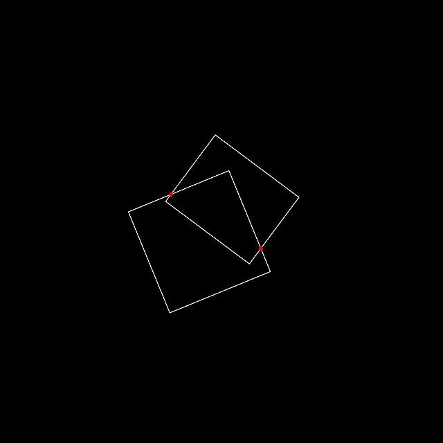
Fork this sketch on openprocessing.
With this in place we can now tackle the task of finding the intersection polygon formed by the two rectangles. If you solely need to determine that two rectangles are intersecting or overlapping you can stop here. If you need to somehow also obtain the polygonal shape that the two rectangles form there's a couple more steps that we need to go through.
Point in Polygon Test
Now that we have the intersection points, how would you go about determining the intersection polygon? In other words, how would you go about finding the vertex points that make up this intersection polygon?
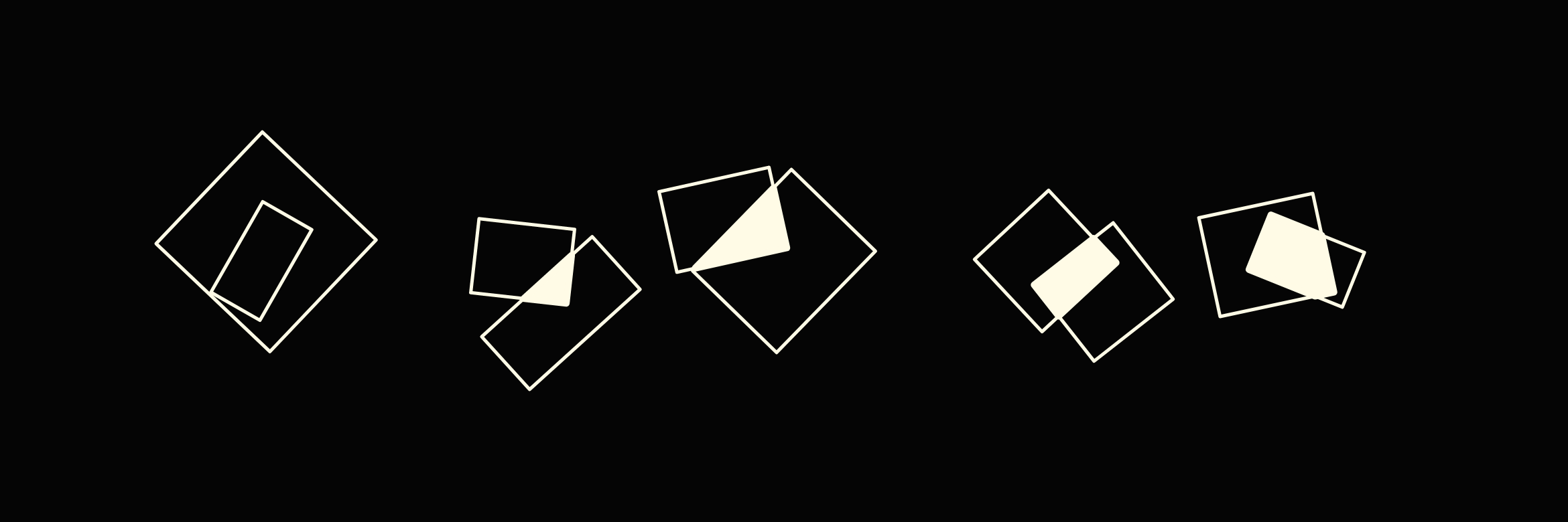
If you observe the figures above, or draw out some on paper, you'll notice that that the vertices of the intersection polygons always consist of the intersection points in addition to the rectangle vertices that protrude one into another. Hence we need some way to determine which vertices of rectangle #1 are contained within rectangle #2 and vice versa. You can also see that there's a special case where one rectangle is completely enclosed within the other, and in that case the method we've developed so far will not be able to determine an intersection. We will have to account for that.
So we need two things, one of them is the line segment intersection code that we already covered in the previous section, in addition to a function that can determine if a point lies within a rectangle or not. The latter will then help us determine which vertices of the first rectangle lie within the second rectangle and vice versa, both of which will contribute to constructing the final polygonal shape. To check if a point lies within a rectangle, or for the matter of fact, within any polygonal shape, we can use an algorithm called ray-casting. Daniel Schiffman has a good introduction to ray-casting:
If you watch the video you'll notice that our line segment intersection code makes a reappearance here as well! Generally ray-casting is useful in a lot of different scenarios, and naturally especially in video games! For our purposes we don't need to develop a full ray-casting example like in The Coding Train's video, we can actually check if a point is within a polygon with a relatively small but ingenious function.
Similarly to the line segment intersection function we can find a point in polygon intersection test function in this stackoverflow answer. The function was adapted from a previous C version by W. Randolph Franklin from his page PNPOLY - Point Inclusion in Polygon Test. He explains everything in great detail, how the function works and how he came up with the method in the first place. The function:
// vs is an array of vertices, [[1,0],[1,1],[0,1],[0,0]] for example
function inside(point, vs) {
    /*
      ray-casting algorithm based on
      https://wrf.ecse.rpi.edu/Research/Short_Notes/pnpoly.html
    */

    var x = point[0], y = point[1];

    var inside = false;
    for (var i = 0, j = vs.length - 1; i < vs.length; j = i++) {
        var xi = vs[i][0], yi = vs[i][1];
        var xj = vs[j][0], yj = vs[j][1];

        var intersect = ((yi > y) != (yj > y))
            && (x < (xj - xi) * (y - yi) / (yj - yi) + xi);
        if (intersect) inside = !inside;
    }

    return inside;
};
The first time I saw this function it just looked like gibberish, but it worked perfectly! Given a coordinate and a set of vertices, it could determine whether or not this coordinate was within the polygonal shape formed by the vertices. Franklin's explanation gives us an idea of how this works:
I run a semi-infinite ray horizontally (increasing x, fixed y) out from the test point, and count how many edges it crosses. At each crossing, the ray switches between inside and outside. This is called the Jordan curve theorem
This algorithm is also known as 'The crossing number algorithm' or the 'even-odd rule'. Basically, if we take a point and draw an semi-infinite ray starting from said point outwards, we can observe how many times this ray crosses the edges of a given polygon. If this number is odd the point lies inside the polygon, if it's even it's outside. I love how this relatively difficult problem is solved by a simple observation.
The main logic of Franklin's method consists of two conditions that firstly check if the y coordinate of the point lies within the y range of the edge we're testing against, and secondly we check if the point is within the half plane formed by that edge. The first condition is simple to verify:
\( (y_i > y) \neq (y_j >y) \)
The second condition is a bit more involved, a good explanation of how it works can be found here. The second check is thus:
\( x < (x_j - x_i) * (y - y_i) / (y_j - y_i) + x_i \)
If both of these conditions hold we can say that the infinite ray cast out from our point crossed the particular edge we tested against. Now remember we need to keep track how many edges that ray has crossed, but since the point can only assume two states, inside or outside the polygon, we can just flip that state whenever the check is true.
Drawing the Intersection Polygon
Alright, so now we've assembled the two pieces of the puzzle and can create a function that can return the vertices of the intersection polygon. We start out by getting the intersection points where the edges of the two rectangles meet each other:
// Get the points where the two rectangles intersect
let intersectionPoints = this.collisionCheck(otherRect)

// If no intersection points then the intersection polygon doesn't exist
if (intersectionPoints.length == 0) {
  return false
}
Next we have to get the points of the rectangles that protrude within each other, for this we will make use of the ray-casting subroutine that we have discussed in the previous section. For our convenience we can make use of the Javascript filter() array method that will return a new array from the elements that pass the condition we pass as a callback function:
// Find points of other rectangle contained within this rectangle
let otherPointsWithinThis = otherRect.computeRotation().filter(v => this.checkIfPointWithin(v));

// Find points of this rectangle contained within the other rectangle
let thisPointsWithinOther = this.computeRotation().filter(v => otherRect.checkIfPointWithin(v));
Now we actually have all of the points that make up the intersection polygon, but to correctly draw it with p5's beginShape() and endShape() we're gonna need them in a clockwise order. We can do this by sorting them around their center point (obtained by averaging their coordinates) by angular value:
// Collect all points
let allPoints = [...intersectionPoints, ...otherPointsWithinThis, ...thisPointsWithinOther]

// Compute center coordinate
let N = allPoints.length
let centerX = allPoints.reduce( (p, c) => p + c.x, 0)/N
let centerY = allPoints.reduce( (p, c) => p + c.y, 0)/N

// Compute angle of each point with respect to the center coordinate
let pointsAndAngs = allPoints.map( p => ({p: p, ang: atan2(centerY - p.y, centerX - p.x)}))

// Sort points by angular value
pointsAndAngs.sort((a, b) => a.ang - b.ang)
Note that this works because rectangles are essentially convex quadrilaterals. For the case where the intersection is somehow not convex this approach would not work. Here's an example where we draw the intersection area and fill it with a color:
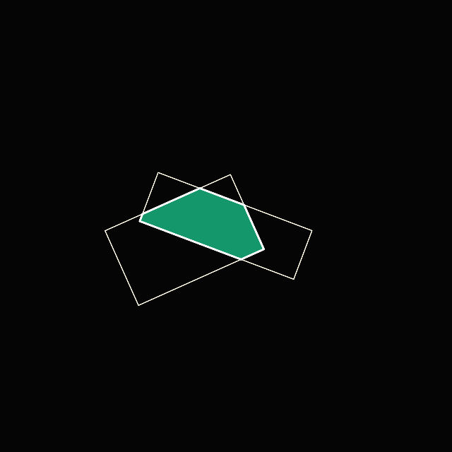
Fork this sketch on openprocessing.
In the next section we'll have a look at how we can extend this to the case of convex polygons.
Beyond Rectangles: Polygon Intersections
Everything we've covered so far has been done in the context of non-axis aligned rectangles. The procedure for determining the intersection polygon we've developed so far can however be extended to convex polygons, with a few modifications! Check out the code of the following sketch to see how it's done, we just have to make changes everywhere where we assumed that loops will go over 4 edges/points:
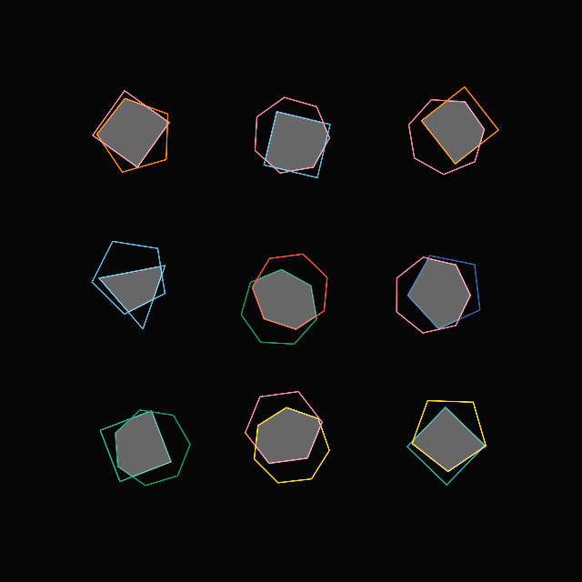
Fork this sketch on openprocessing.
But essentially the only difference is that our makeRect() class becomes a makePoly() class, where the constructor accepts as input a list of vertices. How you create this list of vertices is up to you, because there is no single method to create various kinds of polygons. The example above showcases the intersection of different N-gons.
Technically this can also be extended to concave shapes, but it will fail in certain cases when the points can't be sorted by angular value. Remember when we sorted our points in clockwise order with respect to the center point? In a concave polygon this step isn't applicable anymore, the order is ambiguous, and leads to an incorrect intersection polygon being drawn in some cases. You might have to refresh the sketch a couple times until you get such a shape in the following example:
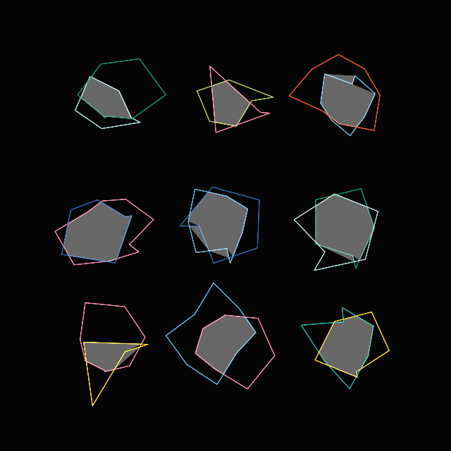
Fork this sketch on openprocessing.
Rather than patching up our method in some hacky way it's probably better to use an already established method that doesn't run into this problem. The Sutherland–Hodgman algorithm is one such method, and is actually fairly similar to the strategy we've developed so far but with the distinction that it gets the order of the vertices right while finding the vertices of the intersection polygon. Read more about why the Sutherland-Hodgeman algorithm works well here, and a compact javascript implementation can be found here.
And lastly I just want to add some links for further reading that are relevant to the topic. Another well known clipping algorithm besides the Sutherland-Hodgman procedure is the Weiler–Atherton clipping algorithm, which is a little bit more complicated though.
Another related topic is also Polygon Decomposition. Sometimes it's necessary to split up a concave polygon into convex chunks. Some tailored approaches are the Mark Bayazit Algorithm. A very easy to integrate javascript implementation of the Mark Bayazit algorithm can be found here, in addition to ear clipping algorithms. These polygon decomposition algorithms however require you to have the points of the concave shape to be in correct order. You can't just pass it a bunch of vertices and expect them to figure out the correct order of the points. In that manner you could also approach the polygon decomposition task with a Delaunay Triangulation algorithm like the Bowyer Watson, but you'd end up with many small triangles, which might not be an efficient way to partition the shape.
Alright, we made it to the end! Thanks a million for reading! If you enjoyed this article consider sharing it with your friends, check out some of my other posts or come and say hello over on Twitter!